
Floating Ball Valve
Floating ball valve is suitable for natural gas, petroleum, chemical and other pipelines as well as oil and gas storage devices, serving as opening and closing devices to cut off or connect the flow of media. This valve can only be used for shut-off or connection purposes and cannot be used for flow regulation.
Floating ball valve is an excellent product produced by our company on the basis of digesting and absorbing advanced technology at home and abroad. It has a more novel design concept and can meet the safety and actual needs of general industrial standards.
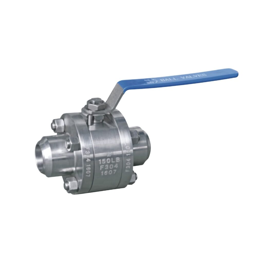
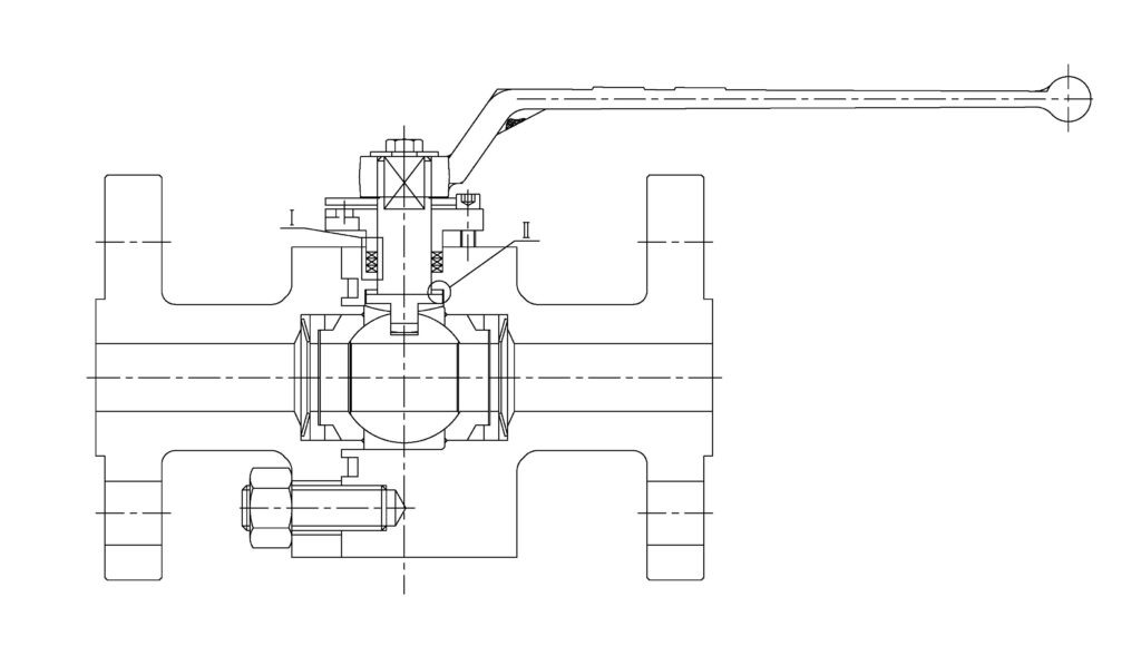
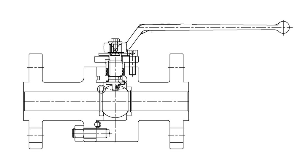
Forged Steel Floating Ball Valve
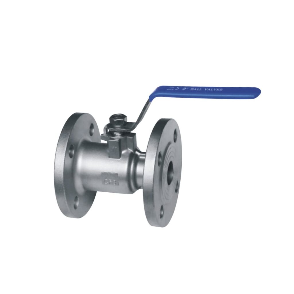
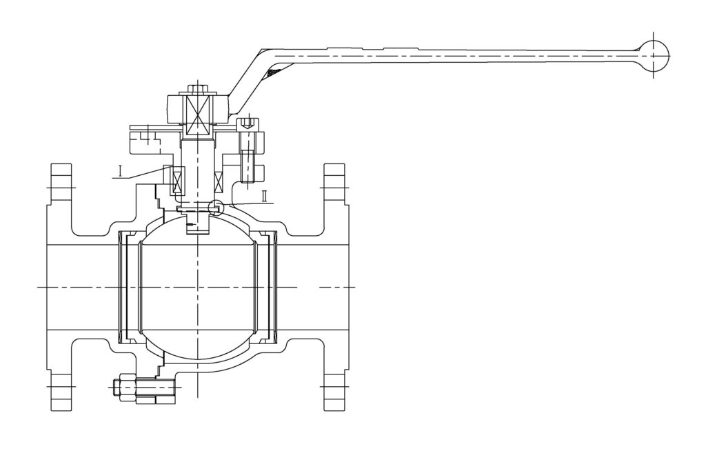
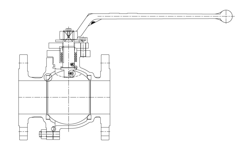
Cast Steel Floating Ball Valve
Floating Ball valve
Structure Features
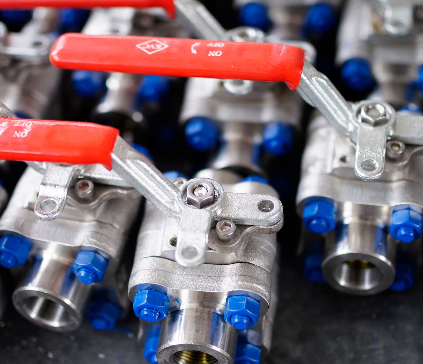
The ball, valve stem, and handle are the moving parts of the valve and are an assembly unit. The head of the valve stem adopts a flat square structure. so that the user can easily and quickly identify the valve in the open or closed state at the position of the handle.
When the handle or flat square of the valve stem is flat with the pipeline axis, the valve is in the open state; when the handle or flat square of the valve stem is perpendicular to the pipeline axis, the valve is in the closed state.
To prevent misoperation of the valve, the valve lock can be used to lock the valve when the valve is fully open or fully closed, especially when the valve is installed in the field or when the process flow does not allow the valve to be opened or closed.
To prevent other personnel from operating the valve by mistake, set the valve position Locking is very important. Therefore, according to the needs of users, the installation of positioning pieces with keyholes in the valve design can meet the safety requirements of users.
Floating Ball Valve Hard Seat Type
| Part Name | Material for cast steel | Material for forged steel |
| Body | WCB / LCB / CF8 / CF8M | A105 / LF2 / F304 / F316 |
| Bonnet | WCB / LCB / CF8 / CF8M | A105 / LF2 / F304 / F316 |
| Ball | A105 / LF2 / F304 / F316+STL / Ni60 / TCC | |
| Seat | A105 / LF2 / F304 / F316+STL / Ni60 / TCC | |
| Stem | F6a / F304 / F316 / F51 / 17-4PH | |
| Stud | B7 / L7 / B8 / B8M | |
| Nut | 2H / 7 / 8 / 8M | |
| Gasket | SS304 + Graphite / SS316 + Graphite | |
| Packing | Flexible Graphite | |
| Seat Seal | Flexible Graphite | |
Cast Steel
Forged Steel
Floating Ball Valve Soft Seat Type
| Part Name | Material for cast | Material for forged |
| Body | WCB / LCB / CF8 / CF8M | A105 / LF2 / F304 / F316 |
| Bonnet | WCB / LCB / CF8 / CF8M | A105 / LF2 / F304 / F316 |
| Ball | A105 + ENP / LF2 + ENP / F304 / F316 | |
| Seat | PTFE / RPTFE / DEVLON / PEEK | |
| Stem | F6a / F304 / F316 / F51 / 17-4PH | |
| Stud | B7 / L7 / B8 / B8M | |
| Nut | 2H / 7 / 8 / 8M | |
| Anti Static Device | SS316 | |
| Gasket | SS304 + Graphite / SS316 + Graphite | |
| Packing | Flexible Graphite | |
Cast Steel
Forged Steel
Request a FREE quote
we look forward to collaborating with you.