GFE Logo

Multi Way Ball Valve

A multi-way ball valve is a type of valve that has multiple ports, allowing for the flow of fluid to be redirected in different directions. It is typically made from stainless steel and has a ball inside with multiple holes that can be aligned with different ports to control the flow of fluid.

Multi-way ball valves are commonly used in applications where the flow of fluid needs to be redirected or controlled in multiple directions, such as in chemical processing, oil and gas, and water treatment industries. They are also used in applications where space is limited and multiple valves would be impractical.

Multi-way ball valves come in various configurations, including 3-way, 4-way, and 5-way valves, with each configuration having a different number of ports. They are also available in different sizes and pressure ratings to suit different applications. These valves are known for their durability and reliability, making them a popular choice for many different industries.

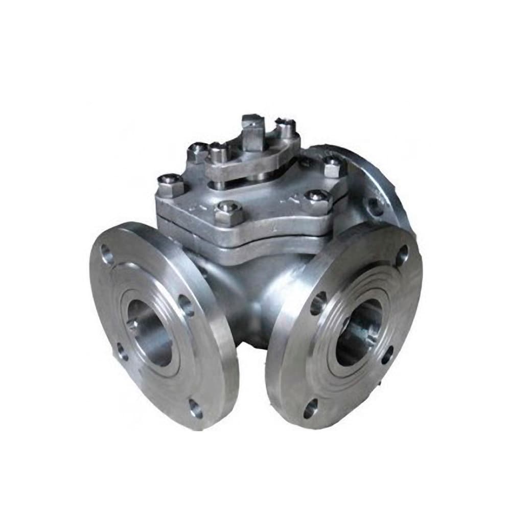
Three Way Ball Valve
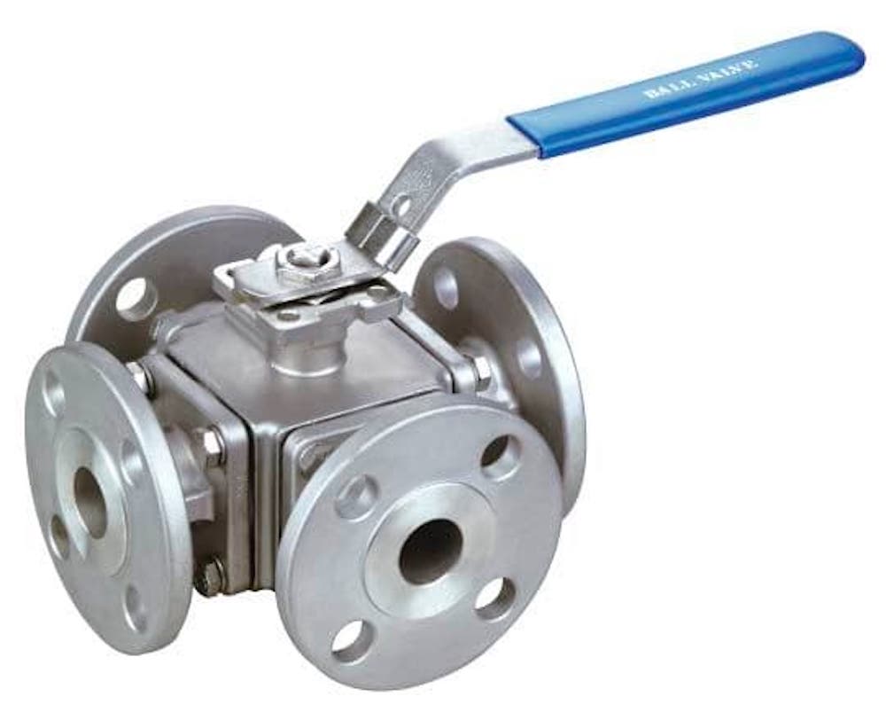
4 Way Ball Valve

Four Way Ball Valve

Contact to Customization Your Valve

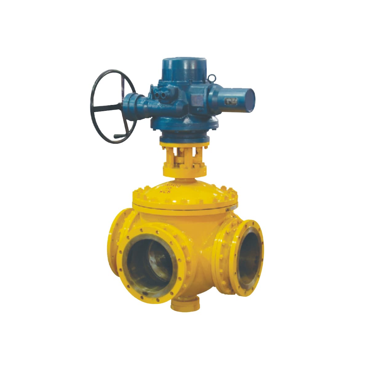
Multi way ball valve

STRUCTURE FEATURES

MULTI WAY BALL VALVE​

The ball, valve stem, and handle are the moving parts of the valve and are an assembly unit. The head of the valve stem adopts a flat square structure. so that the user can easily and quickly identify the valve in the open or closed state at the position of the handle.

When the handle or flat square of the valve stem is flat with the pipeline axis, the valve is in the open state; when the handle or flat square of the valve stem is perpendicular to the pipeline axis, the valve is in the closed state.

To prevent misoperation of the valve, the valve lock can be used to lock the valve when the valve is fully open or fully closed, especially when the valve is installed in the field or when the process flow does not allow the valve to be opened or closed.

To prevent other personnel from operating the valve by mistake, set the valve position Locking is very important. Therefore, according to the needs of users, the installation of positioning pieces with keyholes in the valve design can meet the safety requirements of users.

When the medium passes through the valve, the pressure in the middle cavity of the valve body may push the stem out (or when repairtng the valve. if there is pressure in the middle cavity, the stem and the medium will easily fly out when the valve is dismantleq causing accidental injury to personnel).
 
In order to prevent this from happening, a boss structure is provided at the lower part of the valve stem. In this way, even if the packing and thrust bearing are burned or damaged by other reasons during a fire, the medium pressure in the valve body will make the valve stem boss and the sealing surface of the valve body come into close contact so as to prevent a large amount of medium from being damaged. The purpose of leakage at the packing site.
When operating the valve, due to the friction between the ball and the valve seat of non-metallic materials such as polytetrafluoroethylene, electrostatic charges will be generated and accumulated on the ball.

In order to prevent the generation of static sparks, an anti-static device is specially installed on the valve, and the charge accumulated on the sphere is led out through the electrostatic passage between the sphere and the valve stem, and between the valve stem and the valve body.
In the event of a fire, non-metallic (non-fireproof materials) such as packing andvalve seats will be burnt out A large amount of leaked media may further promote the spread and expansion of the fire.

At this time, the valve's fireproof structure can prevent a large amount of media from leaking. As shown in the following figure, once the valve seat is burned, the ball will directly contact the metal surface on the valve body, thereby preventing a large amount of medium from leaking from the burned valve seat.
The connecting part of the valve body and the left body is sealed by gaskets. In order to prevent the leakage of the seal caused by factors such as fire, high temperature or vibration, the valve body is specially designed to contact the metal-metal of the left body to form a stop flange. Effectively
GFE's many years of ball valve manufacturing experience combined with international advanced technology designed a double-line sealing structure, which can naturally relieve the valve seat and ensure reliable sealing under high low pressure and vacuum environments. When the medium pressure is operating in the low pressure area, the contact area between the valve seat sealing ring and the ball is small, so there is a larger sealing specific pressure to ensure reliable sealing of the valve seat. When the medium pressure runs at a higher level, the valve seat sealing ring and the ball The contact area of the valve is increased, so the valve seat sealing ring can withstand a larger medium thrust to ensure that the valve body is not damaged.

For the ball valve with very low working pressure, considering that the medium pressure cannot ensure the reliable sealing of the valve seat and the pre-tightening force declines after long-term use, so for the low pressure, ultra low pressure or vacuum working conditions, the ball valve is used and the leaf spring is loaded.

The sealing structure of the valve seat ensures the long-term and reliable sealing of the ball valve.
The seat sealing structure of medium and high temperature ball valves uses parapolystyrene as the sealing ring and can be used at a temperature of 300°C, while the ball valve with a metal seal and high temperature resistant composite material structure design can be used at higher temperatures. This structure has a one-way sealing function.
When the medium in the middle cavity of the valve changes due to the pressure of the piping system or the temperature of the medium, and the pressure in the middle cavity rises abnormally, the medium in the middle cavity can rely on its own thrust to push the valve seat to automatically release the pressure, thereby ensuring the valve Security.
GFE's ball valve has two series of diameter: full diameter and reduced diameter to meet the different needs of users.


The internal diameter of the channel of the full-bore ball valve is the same as the internal diameter of the pipeline, and the fluid resistance is minimal, which is convenient for pipeline cleaning.


The weight of the reduced diameter
series ball valve is only about 70 % of the same diameter ball valve, which can effectively reduce the cost and price, and its fluid resistance coefficient is only about 1/7 of the same diameter stop valve, so the reduced diameter ball valve is widely used abroad.

Request a FREE quote

we look forward to collaborating with you.

Request a FREE quote

we look forward to collaborating with you.