
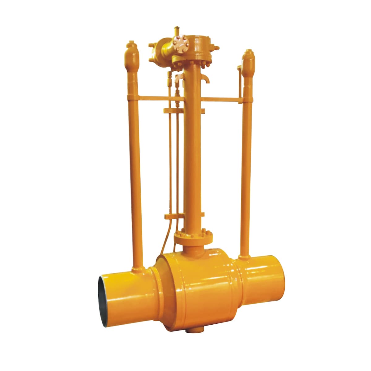
Fully Welded Ball Valve
Fully welded ball valves, also known as welded body ball valves, have their valve bodies permanently welded around the ball and stem assembly. This creates a single integrated unit with no possibility of leaks or fugitive emissions from body seals.
Welded body ball valves provide maximum safety and environmental assurance for applications involving hazardous or toxic fluids. They prevent escape of fluids even in the event of seal failure. They are also fire-safe since there are no body seals that can burn or damage during a fire.
However, the welding process makes the valves more complex and expensive to manufacture compared to standard ball valves. It also prevents disassembly of the valves for servicing the ball and seats. The valves must be scrapped once the ball or seals become damaged or worn out.
Fully welded ball valves are used for the most critical applications such as emergency shutoff valves in pipelines, isolation valves in chemical processing plants, and control valves for nuclear facilities. Only the highest performance and most durable valves are suitable for such applications due to their non-maintainable nature.
Fully welded ball valves provide higher pressure ratings compared to standard ball valves. They are available in sizes up to 56 inches and above with some specialized for high temperature services up to 1000°F. Automated valve solutions are popular for remote operation or modulation of critical welded ball valves.
Fully welded ball valves provide the ultimate assurance in terms of sealing and safety for high-risk applications in the oil & gas, chemical and nuclear industries involving hazardous substances. Their specialized and premium design is suitable for the most critical piping services. For maximum reliability and performance, only the best fully welded ball valves will suffice.
Fully welded ball valve
STRUCTURE FEATURES
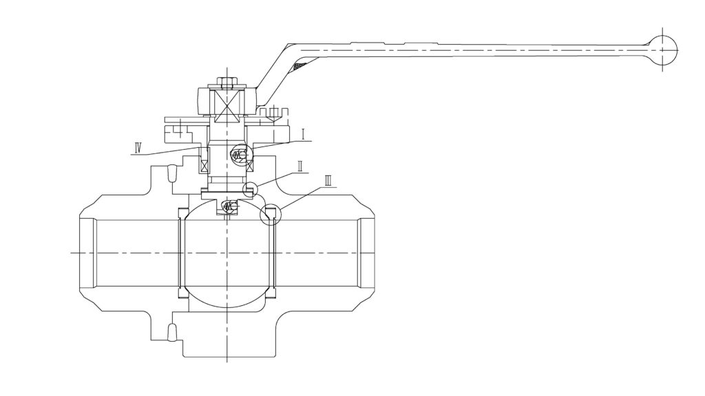
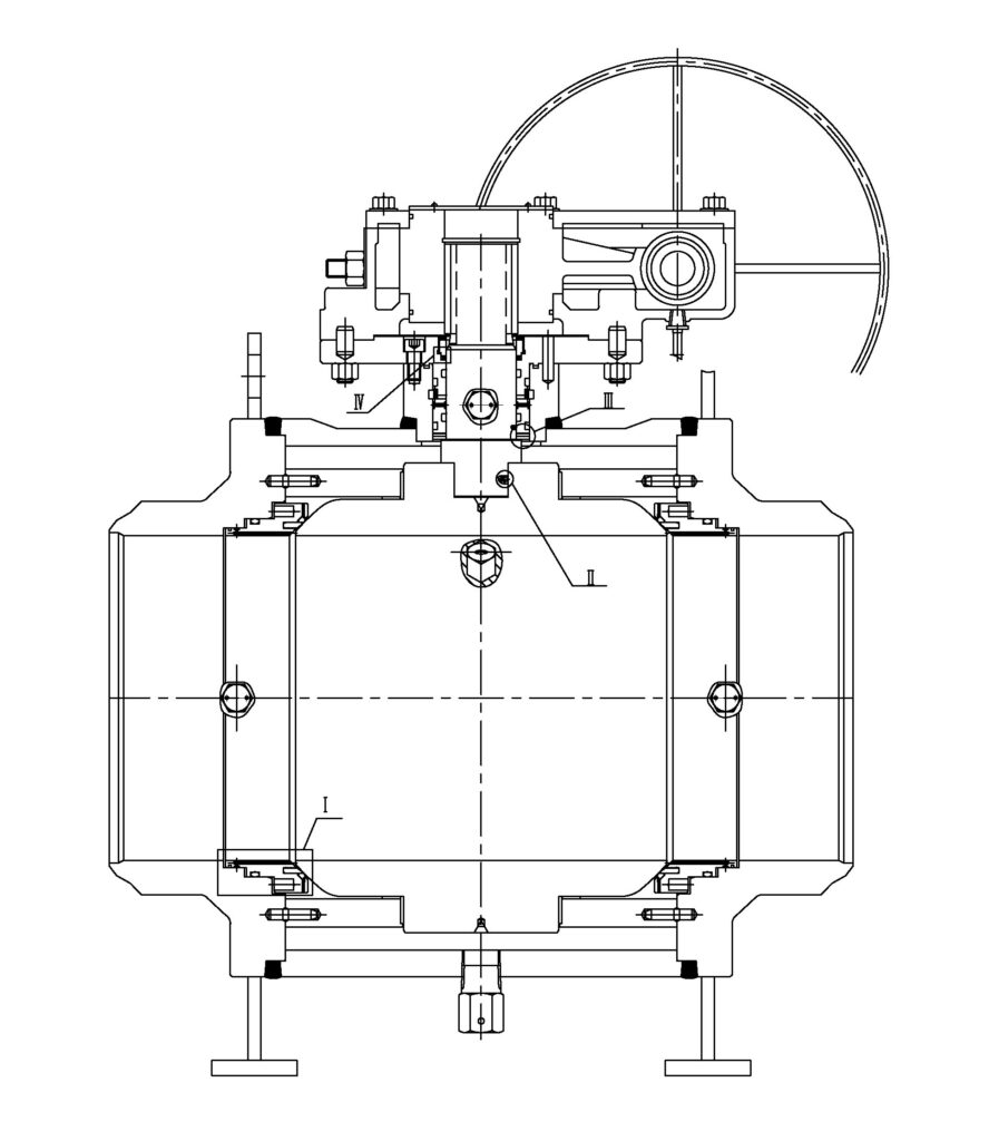
The ball, valve stem, and handle are the moving parts of the valve and are an assembly unit. The head of the valve stem adopts a flat square structure. so that the user can easily and quickly identify the valve in the open or closed state at the position of the handle.
When the handle or flat square of the valve stem is flat with the pipeline axis, the valve is in the open state; when the handle or flat square of the valve stem is perpendicular to the pipeline axis, the valve is in the closed state.
To prevent misoperation of the valve, the valve lock can be used to lock the valve when the valve is fully open or fully closed, especially when the valve is installed in the field or when the process flow does not allow the valve to be opened or closed.
To prevent other personnel from operating the valve by mistake, set the valve position Locking is very important. Therefore, according to the needs of users, the installation of positioning pieces with keyholes in the valve design can meet the safety requirements of users.
Materials for Main Parts
| Part Name | Material for cast | Material for forged |
| Body | A105 / LF2 / F304 / F316 | |
| Bonnet | A105 / LF2 / F304 / F316 | |
| Ball | A105 + ENP / LF2 + ENP / F304 / F316 | |
| Seat | PTFE / RPTFE / DEVLON / PEEK | |
| Stem | F6a / F304 / F316 / F51 / 17-4PH | |
| Stud | B7 / L7 / B8 / B8M | |
| Nut | 2H / 7 / 8 / 8M | |
| O-Ring | VITON AED / HNBR AED | |
| Anti Static Device | SS316 | |
| Gasket | SS304 + Graphite / SS316 + Graphite | |
| Packing | Flexible Graphite | |
Floating Type
Trunnion Type
Request a FREE quote
we look forward to collaborating with you.